Runout, in regard to industrial machinery, is most commonly defined as a deviation from a rotor’s true circular path or concentricity in a machine shaft or coupling. Visually, the shaft or coupling (or both) will typically “wobble” slightly throughout their rotation.
Runout typically causes a loading/unloading cycle that’s repeated during every rotation of the shaft. This type of scenario can cause many issues such as accelerated wear on bearings, seals, and couplings, as well as increased load on the motor, reducing its efficiency and shortening its life span. Here is a list of a few things to consider when measuring for runout.
- Use a traditional dial indicator or an electronic runout probe to obtain your readings. Make sure your indicator base (typically magnetic) is securely fixed to a fully stationary machine surface or similar to ensure there will be no movement in the base while taking your readings.
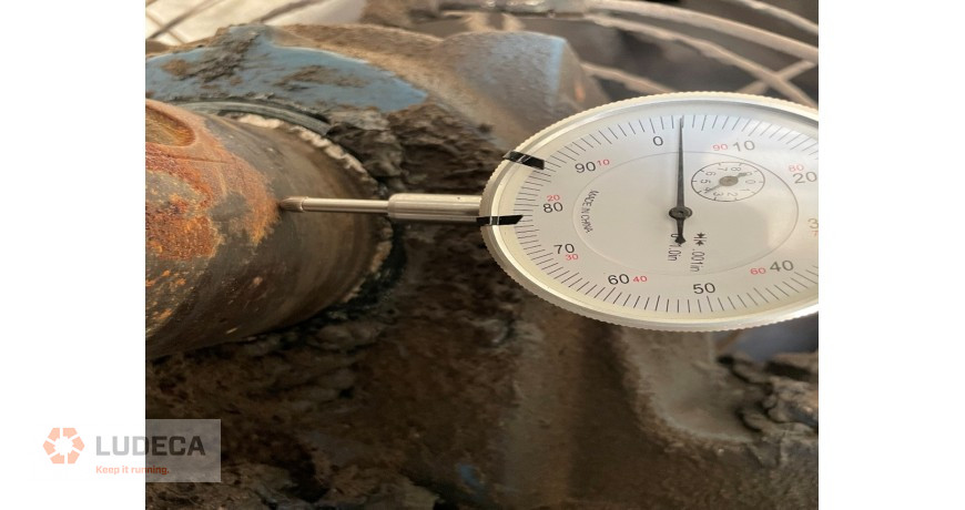
- Typically, you will start with an indicator mounted perpendicular to the shaft with the probe on the outside diameter or rim of the coupling hub, then rotate the shaft. This will tell you if there is runout in your equipment but will not identify whether the runout is in the coupling hub, the shaft, or both.
- Runout can occur from several causes. You could have a bent shaft. Your coupling hub bore could be off center. Your shaft could be undersized, or your coupling hub bore oversized, causing the coupling hub set screws to pull the coupling hub off center during installation. In some cases, your coupling hub bore could even be skewed, meaning the center of the bore on one side of the hub is in a different location than the center of the bore on the other side. To verify this, take axial readings. The probe should be on the coupling hub face, parallel to the shaft.
- How much runout is too much? Generally, we look to have runout of 0.002″ or less as an industry standard; however, this depends on several factors, including speed and drive type. Typically, runout of 0.005″ or more is considered excessive.
So, How Can We Catch Potential Runout Defects Before They Cause Major Issues?
- The answer is condition monitoring and quality vibration analysis. There are some scenarios where performing a runout check should be part of the routine for the task at hand. In particular, runout should be checked during pre-alignment procedures in both direct drive and belt-driven machinery. Many times, however, the issue occurs before we’ve had a reason to check the runout.
- Using Ludeca’ s lineup of Betavib vibration data collectors and analyzers will allow you to catch runout issues early. Runout will typically show up in the spectrum as a dominant 1× frequency and will likely have elevated 1× vibration in the axial direction as well. We can use phase analysis to further distinguish between runout, misalignment, and unbalance.
Filed under:
Vibration Analysis by Tyler Wilson