Setting the correct lines of resolution (LOR) can sometimes be challenging. In the example below we have a single-stage increasing gearbox. The gearbox is designed with three individual shafts (input shaft, intermediate shaft, and output shaft), all enclosed within a single gearbox housing.
The speed of the input shaft is constant at 29.93 Hz (1796 rpm) and attached to this input shaft is a pinion gear with 88 teeth. The pinion gear runs in mesh with a gear with 27 teeth which is mounted onto the intermediate shaft. This results in a gear mesh frequency of 2633.84 Hz (158,030.4 cpm). Now we need to determine the required Fmax. Therefore, we simply multiply our calculated gear mesh frequency times 3.25, which gives us an Fmax of 8559.98 Hz (513,598.8 cpm). In the software, we can’t select the value 8559 Hz, so we’ll need to select the next higher value which results in a Fmax of 10kHz. The next step in the process is to determine what the speed of the intermediate shaft is, and we can do this by using the following formula:
Intermediate shaft speed = 29.93 Hz × 88 teeth = 2633.84 Hz / 27 teeth = 97.54 Hz, or 5852.4 cpm.

We now need to decide how many lines of resolution we are going to need since in this gearbox we have two closely spaced running speeds. We have the intermediate shaft speed which is running at a constant speed of 97.54 Hz, and we have the output shaft speed which is variable. When the boiler feed water pump is operated at 100%, we have an output shaft running speed on the gearbox of 94.33 Hz or 5660 rpm. There is only 3.21 Hz or 192.6 cpm between the two shaft speeds within the gearbox so our lines of resolution setting will need to be set high enough so that we separate them while performing analysis. With a Fmax setting of 10kHz, we will need to have a minimum of 3200 lines of resolution so we would have two discrete peaks for the two shaft running speeds.
Fmax 10kHz / 3200 = 3.125 Hz, but to be on the safe side I would recommend selecting the next higher resolution setting [6400 line] which will allow a 1.56 Hz [96.3 cpm] resolution which is sufficient to easily see the two different shaft running speeds for accurate analysis.
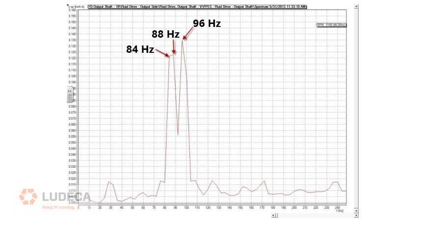
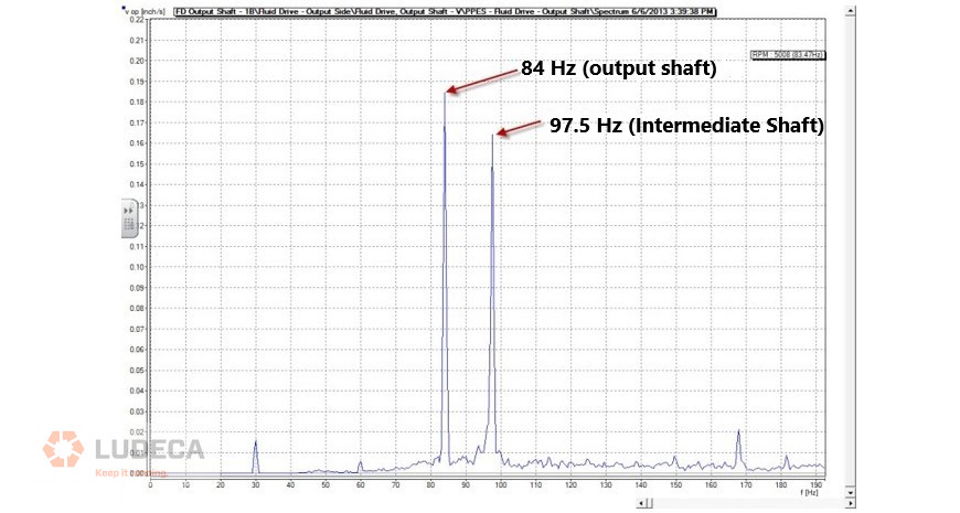
Below are examples of the resolution, the first not being set high enough (top) and the second with the resolution set correctly (bottom).
Improper resolution settings resulting in a flat top peak for the output shaft speed:

Correct resolution setting (allowing for the separation of the two shafts turning speeds):

Filed under:
Vibration Analysis by Dave Leach CRL CMRT CMRP
