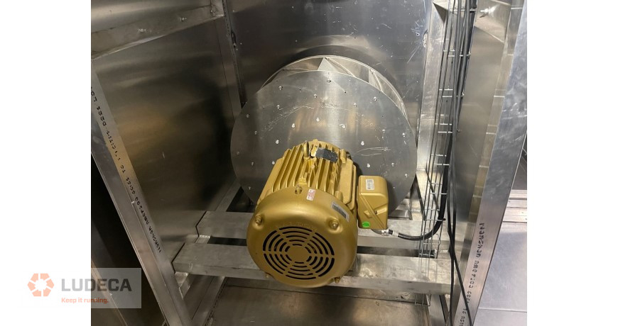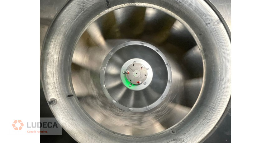
- All rotating equipment shall be designed and constructed so that its first critical speed is at least 125 percent of the maximum design speed for the equipment (i.e. rotating equipment shall operate at speeds less than 80 percent of their true critical speed). Unless otherwise required, equipment shall be balanced according to the recommendations given in this section.
- Equipment components such as motors, pump rotors, fan wheels, etc. shall be factory balanced both statically and dynamically, to meet the field balance requirements described below.
- All balance reports shall be referenced in inches per second (ips or in/sec), zero to peak. A balance report shall be provided for each piece of equipment tested.
- Balance of Critical Equipment:
All equipment located in areas that may be sensitive to process vibration shall be classified as “critical” equipment for the purposes of this standard.
b. Critical fans shall include all fans greater than 10hp (7.5 kW) located within a fab building including recirculating air fans, makeup air fans, and exhaust (scrubbed, solvent, and general) fans.
c. Factory balance of critical equipment: All critical equipment shall be factory balanced. Vertical and horizontal vibration shall be less than that shown in Table 3.8A for “Critical” equipment at all frequencies from 2 to 5000 Hz.
d. Field balance of critical equipment: Shall be checked following field installation to the same standard as the factory balance. Adjustments shall be made as necessary to bring them within the specified limits. A balance report shall be provided for each piece of equipment tested.
e. Rotors of all critical fans shall be whirl-tested to 125 percent operating speed and balanced to ASHRAE Standards or better.
f. All critical equipment shall be field tested in accordance with International Standard ISO 10816-1 and 10816-3 or the most current edition of ANSI Standard S2.41 by an independent third party after installation and under actual operating conditions. - For all equipment, measurements shall be taken on each bearing on all three axes: vertical, horizontal, and axial. Measurements shall be taken on the equipment bearing caps in three orthogonal directions: parallel to the shaft in the horizontal plane and perpendicular to the shaft in both the horizontal and vertical planes.

Balance Methods:
If weights are attached, they shall be either welded metal, bolted mass, or special heat-treated resin. Weights shall not interfere with the aerodynamic functionality of the machine. Weights shall not be attached to the fan or impeller blades, but instead to the side plane to which the blades/vanes are attached. Weights shall be attached at the farthest possible point from the centerline to minimize the amount of additional mass required to be added.
Materials used as balance weights shall be able to withstand the type of media in the system; dissimilar metals are not allowed due to corrosion problems.
Thank you Brian Franks with JetTech Mechanical for sharing this very educational information with us!
Download our 5-Step Balancing Procedure a simple and effective procedure for doing field balancing.
Preparing for the Balancing Job: A Few Things to Keep in Mind
Filed under:
Balancing by Diana Pereda
