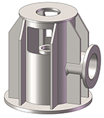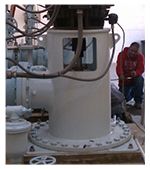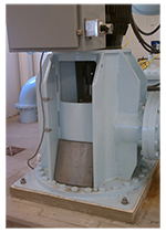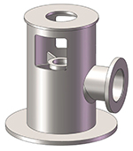
Smith Pump modeled the discharge head in Solidworks. Since the measured natural frequency was 1500 CPM, and the pump operating range was 1500 to 1800 RPM, we wanted to lower the natural frequency below 1500 CPM. We knew by removing stiffeners from the discharge head we would lower the unit’s natural frequency. We removed stiffeners and ran a finite element analysis to determine how much we would lower the natural frequency. Our model study showed that by removing all the external stiffeners and half of all the internal stiffeners we would lower the natural frequency by 30%. Pump #2 was removed and its discharge head was modified by removing stiffeners.

Pump #2 was put back into service with its modified discharge head and vibration testing was performed. The new bump test data gave a measurement of 86 CPM in line with discharge. The vibration measured at 50 HZ at the top of the motor was 0.05 in/sec RMS. The vibration dropped from 0.47 to 0.05 in/sec RMS.
In conclusion, determining a unit’s natural frequency is very important when designing a vertical turbine pump. Every fabricated steel discharge head that Smith Pump makes is modeled in Solidworks and goes through a finite element analysis to make sure the unit’s natural frequency (mainly discharge head and vertical motor) is 25% away from any running speeds. In this example, the discharge head (built by others) was too stiff and had a natural frequency at the pump operating speed causing high vibration. Since Pump #2 was so successful, we are currently modifying Pumps #1 and #3 the same way. Common sense tells us that the stiffer and stronger the discharge head the better, but this case study clearly shows us that is not the case!
Special thanks to our customer Josh Jurgensen, service engineer at Smith Pump Company for sharing this case study with us!
Filed under:
Articles and Case Studies, Vibration Analysis by Yolanda Lopez


