RELIABLE PLANT • February 2012
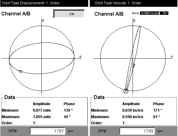
Orbits have historically been used to measure relative shaft movement within a journal-type bearing. The shape of the orbit told the analyst how the shaft was behaving within the bearing as well as the probable cause of the movement. This was accomplished using proximity probes usually mounted through the bearings with a 90-degree separation and a tip clearance set to around 0.050 inches. With today’s modern analyzers, it is possible to also collect an orbit using case-mounted velocity probes or accelerometers to see how the machine housing is moving. Another way of putting it would be the orbit represents the absolute path in space that the machine housing moves through (see Figure 1).

Read my entire article “Using Orbits for Condition Monitoring”.
Filed under:
Articles and Case Studies, Vibration Analysis by Gary James CRL
