When a failure occurs, one of two things happen:
- A Failure Analysis program kicks in to figure out what truly caused the failure in order to eliminate the condition that caused that specific failure. Or…
- The easiest thing to see gets blamed. That “blame game” can be influenced by factors that have nothing to do with that specific failure, like past experiences, mechanical prejudices (preferring one brand over another), personal differences (doubting another’s workmanship), and even possibly looking to sweep the whole problem “under the rug” to distance someone from that blame.
When it comes to the failure of a crankshaft, or any other component of a rotating assembly, alignment is one of the things often brought up, like a “low hanging fruit”. This is why having a proper procedure, such as our 5-Step Shaft Alignment Procedure is so important. Going through each step of that procedure will help spot and eliminate the defects that could cause the equipment to experience that failure. And once the work is completed, the documentation portion becomes a record of how the job was done in order to help with any Failure Analysis.
Let’s take a look at some failure modes and see what could have caused the issue instead of just saying, “must have been a bad alignment.”
High Bearing wear at the front of an engine with Oil Analysis showing Tin, Aluminum, and Copper
Since this is nowhere near the coupling, alignment would be hard to blame, but there are other things to consider when looking for causes. Do the belts have too much tension? Was Soft Foot or Base Deflection overlooked? Has the Harmonic Balancer failed? Has the engine been reconfigured to run faster than originally rated and not have the supporting parts replaced to accommodate that increase in RPM? The bearings are coming apart and the cause must be found. Download an outline of types of Soft Foot including causes and corrections.
High Bearing wear in the middle of an engine with Oil Analysis showing Tin, Aluminum, and Copper
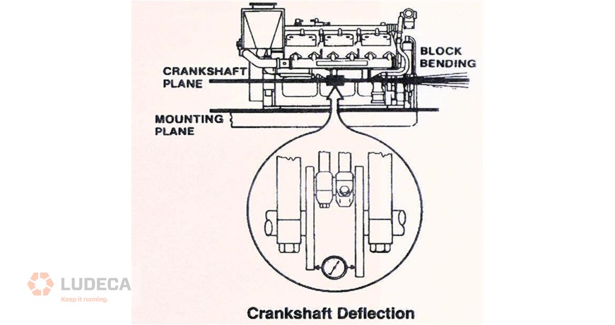
The problem is getting closer to the coupling so it cannot be ruled out, but it would need to be a large amount of misalignment to cause the bending of the shaft and a proper alignment procedure with proper tools and training would help eliminate that. What else would cause this condition? How about web deflection? Are the middle feet of the engine properly mounted and torqued?
High Bearing wear at the rear of an engine with Oil Analysis showing Tin, Aluminum, and Copper
Now we are talking a lot more about the alignment. Since the coupling is right next door, we have to be very aware of what that alignment looks like. How was the equipment aligned before, and what does the report show for an “As Left” condition? Has the equipment shifted or is the base and foundation degrading to the point that it can no longer support the weight and power delivery on this package? Was Thermal Growth calculated correctly and properly compensated for? All of these factors should be addressed with the application of a proper alignment procedure. Download an overview of 4 common thermal growth methods including advantages and disadvantages.
These are just some of the issues that have been discussed when a failure occurs, and in a lot of those cases, alignment got an unfair amount of the blame. If a procedure is in place to perform alignments correctly, and documentation has been properly archived, Failure Analysis should go much smoother to find the actual cause of the failure, instead of just going for the “low hanging fruit”.
Filed under:
Alignment by Chris Greene CRL