Most of us know that accurate shaft alignment will increase the life of machine components such as bearings, seals, and couplings, and thereby help prolong the life of your equipment. However, performing a shaft alignment can be cumbersome at times, especially aligning multiple machines in a machine train at once. A multi-coupling train is an alignment that should be approached carefully.
An “as found” measurement should always be taken on all the couplings before any shimming or moves are made. This will provide a clear picture of what the misalignment is throughout the whole train. It will also decrease the likelihood of ending up in a base-bound or bolt-bound situation, which is a very common occurrence when doing a machine train alignment. When the stationary machine in a train is angled on its base, the other machines in the train will need to be aligned to this angle.
The goal is to minimize the amount of movement required and still achieve excellent alignment at each coupling. The Rotalign® Ultra’s Move Simulator has the capability to show potential correction alternatives before actually performing them. In this particular alignment at a power plant, we had a Pump-Gear Box-Motor train. After taking readings at both couplings we used the Move Simulator to determine that it was possible to obtain alignment within tolerances at both couplings by only shimming and moving the middle machine. Figure 1 shows the Rotalign Ultra iS set up at one of the couplings.
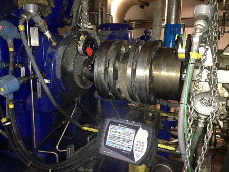
Fig. 1: Rotalign Ultra iS set up at one of the couplings
Figure 2 shows the as found readings for the machine train:
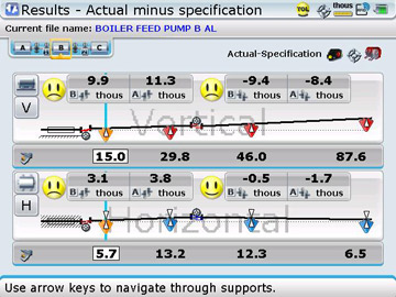
Fig. 2: “As found” alignment of the machine train
We then opened the Rotalign Ultra’s Move Simulator. Figure 3 shows the initial screen, zoomed in to just the Vertical alignment situation:

Fig. 3: Move Simulator initial screen
We proceeded to ‘simulate’ removing shims out the right feet of the middle machine (Machine B) and determined that by removing 8 mils it was possible to get the alignment at Coupling Two within tolerances. Figure 4 shows that screen:
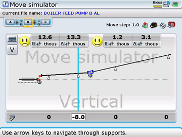
Fig. 4: After simulated shim removal of 8 mils at right feet of Machine B
We then proceeded to simulate removing shims out the left feet of the middle machine (Machine B) and determined that by removing 10 mils it would be possible to get the alignment at Coupling One within tolerances while still maintaining an in-tolerance condition at Coupling Two. Figure 5 shows that screen:

Figure 5: After simulated shim removal of 10 mils at left feet of Machine B
Shimming was executed as suggested by the Move Simulator and after one shim change and one horizontal correction new readings were taken and the alignment results shown in Figure 6 were obtained:
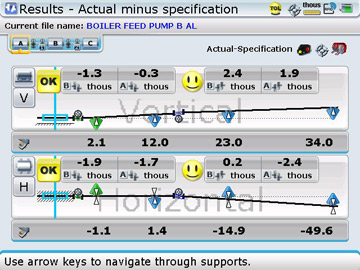
Figure 6: Final alignment after just one shim change and horizontal move of Machine B
Filed under:
Alignment by Adam Stredel CRL