A recent customer visit offered us an opportunity to provide dynamic measurement on a large Combustion Gas Turbine Generator package. This machine has a history of excessive vibration following startup and continuing into steady-state operations. It was suspected that the changes in the alignment condition of this machine were the reason for the excessive vibration. It was a great time to monitor positional change from field data and compare them to the OEM recommendation.
 We used the PERMALIGN® System. This laser-optical system can be used to continuously measure the alignment condition during running conditions. The measurement data will reflect the machinery’s actual misalignment behavior. These results can be used to determine the optimal alignment targets.
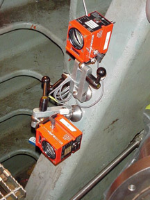
The PERMALIGN monitors emit an infrared laser beam that is reflected back to a detector located in the laser head via a roof prism. The PERMALIGN monitors are positioned on the machines’ bearing housings so as to remain stationary. The roof prisms are mounted on the machines as well. Any movement of the prisms in their primary orientation results in corresponding changes in the position of the laser beam back at the detector. This change in the laser beam’s position on the detector reflects the change in the position of the prism in its primary orientation.
PERMALIGN monitors were set up to monitor the Power Turbine (Horizontal and Vertical), Generator Drive End Bearing (Vertical), and Generator Exciter End Bearing (Vertical). The PERMALIGN transmitters in the generator enclosure were mounted on pedestals fabricated for this particular machine. The roof prisms for the generator were mounted directly to the split line of the bearings. A mounting plate was fabricated from ¼” thick steel and bolted to the power turbine housing. The roof prisms were mounted to this plate. All the PERMALIGN monitors were linked to a computer and set to zero.
The data collection process was started and the machine was placed in service and loaded. The machine was allowed to heat up. The unit was then shut off and allowed to cool back to its ambient fully dormant condition. As the machine cooled, the laser tracked back to the center of the detector. The machine was restarted, loaded to 10 MW, and allowed to reach normal operating conditions.
Data collected on the generator was very smooth, repeatable, and consistent with the expected changes in the bearing elevations.
PERMALIGN data collection measured the following changes in the positions of the turbine and generator: (Results are as viewed by a laser shaft alignment system, looking at the turbine shaft from the generator’s point of view. Positive values indicate growth in the 12 o’clock direction and 3 o’clock directions.)
- Power Turbine Horizontal: +27 mils
- Power Turbine Vertical: +27 mils
- Generator DE Bearing: +15 mils
- Generator EOD Bearing: +7.5 mils
The positional changes were automatically graphed in the laser system and a set of cold alignment targets was determined. Those targets are as follows:
OEM Recommended Targets:
Target Vertical Offset: +52 mils +190mils
Target Vertical Angularity: +2.7 mils/10″ +8.0 mils/10″
Target Horizontal Offset: +51 mils 0.0 mils
Target Horizontal Angularity: +1.8 mils/10″ 0.0 mils/10″
A review of the OEM recommended targets for this machine from documentation provided by our customer indicates targets of +190 mils VO (Vertical Offset) with a specified coupling gap of 13 mils at a face diameter of 16.375″ (+8.0 mils/10″ Vertical Angularity.) No horizontal alignment targets are identified in the turbine manufacturer’s literature. The targets are to be measured and set at the load equipment coupling (generator coupling.)
Finally, the unit was aligned using the targets from the PERMALIGN test using a ROTALIGN® ULTRA iS laser shaft alignment system. The unit was started and the vibration levels were well below acceptance limits at operating conditions.
Filed under:
Alignment by Steve Lochard CRL