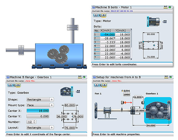
Right angle drives or 90-degree gearboxes are very common in the industry. These are speed reducer/increaser machines with an output shaft exiting at a 90-degree angle with respect to the input shaft. In some cases, the 90-degree turn stays on the horizontal plane. This is great because the alignment can be treated as a machine train alignment.
However, when a gearbox has an output shaft emerging vertically, the alignment becomes much more complex. This coupling should be treated as a vertical alignment, where the support of the machine is a flange, whose feet are visualized as being the flange bolt pattern where shimming takes place to correct angular misalignment. This fictitious flange is to be placed at the plane of the feet, where the shims are to be inserted or removed. Having a system that will allow you to customize the bolt pattern and bolt positions is critical in this case. Depending on the existing conditions at the gearbox feet, you may wish to choose a positive, negative, or optimized (+/–) shimming solution in order to minimize the axial effect of any shimming corrections. Offset corrections are performed by moving the machine laterally only after angularity has been corrected.
What if the shaft is not in the center of the machine but offset to one side? With the proper laser alignment system, the user can set up the alignment job so that the true shaft geometry within the machine frame is correctly represented. Only in this way can we obtain the proper corrections at the machine’s feet.

Filed under:
Alignment, Maintenance Tips by Adam Stredel CRL
