
We previously discussed, Best Practices: Machinery Alignment Shimming Part I. In this blog, we discuss shimming techniques, choosing the right shims to use, and more.
Note: This blog post is an abridged version of a longer article on this subject published by the author in 2013.
SHIMMING TECHNIQUE
Always sandwich your thinner shims between thicker ones to protect them. In fact, if you have to shim 26 thousandths, choose to use a 20 and two 3s, rather than a 25 and a 1 alone.
Always insert your shims until you feel them touch and then withdraw them slightly. This way you know for sure that you are not letting the slot of the shim get caught in the threads of the anchor bolt.
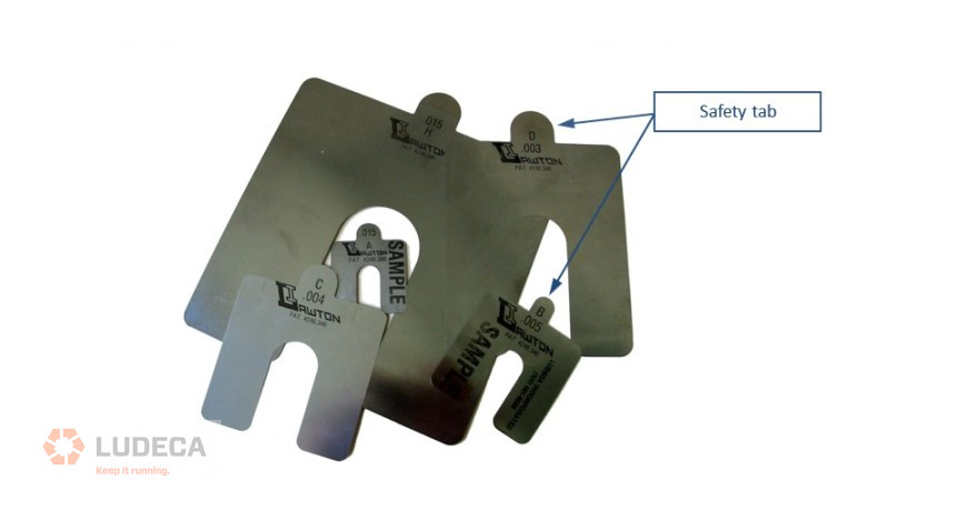
Always handle your shims by grasping them by the safety tab (see Figure 1); never let your fingers get under a machine foot while the machine is being pried up or lifted!
CHOOSING THE RIGHT SHIM TO USE
You can choose your shim size by the horsepower of the machine; however choosing by the slot size is fine too. The foot’s surface area is less important. It is a myth that you have to support the entire surface area of the machine foot with the shim. You only need to support the load zone around the anchor bolt. See Figure 2 for an illustration of the load zone and the area that should be supported by the shims. Most machine feet are made much larger in surface area than what is strictly necessary to support the mass of the machine and its operational load stresses. So, if a machine foot is larger than a given size of a shim, but the shim adequately supports the load zone around the hole in the foot, you do not have to worry if the outer edges of the foot overhang the shim a bit—that is perfectly okay.
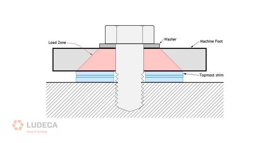
The load zone (depicted in red) is defined as a cone approximately 45 degrees from the edge of the flat washer under the anchor bolt through the thickness of the machine foot. As long as your topmost shim supports the surface area defined by the cross-sectional cut of this cone under the foot, you are adequately supporting the load zone of the machine’s foot and do not need to support any excess surface area under the foot.
SHIMMING MISTAKES
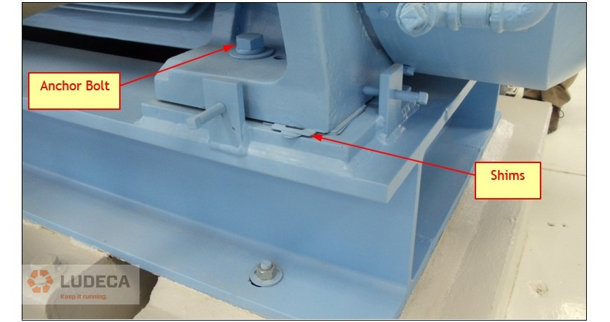
Figure 3 shows an example of how not to shim a machine: Too many shims were used and the shims do not support the load zone of the machine’s foot around the anchor bolt. Moreover, the Size ‘A’ shim used on top of the shim stack is too small for a motor of this size. When the anchor bolt of this foot is tightened, the foot will be stressed, distorting the machine’s frame and altering the internal alignment of the bearing bores, as well as affecting the air gap between rotor and stator. Note too that the motor was painted in situ, covering the shims and jackscrews in paint and also allowing paint to get under the foot. These are all bad practices.
UNUSUAL CIRCUMSTANCES: STEP-SHIMMING
Sometimes, a machine will have feet that are significantly angled with respect to the contact surface of the base plate or sole plate supporting them. This can be caused when the feet are accidentally bent, or when the machine is “rolled” to accommodate a horizontal misalignment problem (definitely not a best practice!) Tightening the anchor bolts under these conditions would force the feet flat to the base, thereby distorting the machine and increasing the radial load on the bearings. This affects air gap clearances between internal components and places undue stress on the feet or other machine parts. How do you solve this problem? The best way, of course, would be to re-machine the base plate, sole plate, or undersides of the machine feet in such a way as to eliminate the lack of coplanarity. However, this may not be practical or economical to do. This leaves us with the only other possible solution: step shimming.
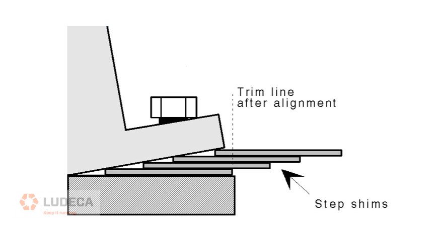
Step shimming requires several thinner shims to be carefully inserted between the machine’s foot and its support surface in such a way that they are offset from one another in step fashion. This fills the tapered gap between the underside of the foot and its support plane as evenly as possible, as illustrated in Figure 4. This may require you to use more than three shims overall, but as with everything, there is always an exception to the rule and here the benefits of doing this outweigh the disadvantages. Although not elegant, the step shimming solution is expedient, easy and economical, and will prevent a much more serious problem resulting from machine frame distortion, allowing your machines to run satisfactorily until your next major outage.
The angles illustrated in Figure 4 are vastly exaggerated to illustrate the concept. It goes without saying that we are talking about angles with a rise over run of just a few thousandths of a inch per inch. To step shim correctly, choose a shim thickness that will allow you to stack no more than four shims to fill the uneven air gap between the underside of the foot and its support surface. Step shimming works well since the angles involved are sufficiently small enough to fall well within what is known as the ‘swedge’ angle for the coefficient of friction of the materials involved. This means as you tighten the anchor bolts and apply load to the shims, they will tend to remain in place rather than “squirt out” like watermelon seeds. Once the step shimming task is complete and the alignment of the machines has been rechecked with all anchor bolts tight, do not neglect to trim off the excess part of the shims protruding out from under the edge of the machine’s foot to prevent possible injury.
It also goes without saying that if the time and resources are readily available, you should consider re-machining the undersides of the feet or the contact surfaces of the base plate, or making a tapered “dutchman” shim for the foot. Keep in mind, too, that the “bent” foot may be symptomatic of a larger problem with the machine, such as internal damage if it resulted from the machine being dropped in transport or installation. If the angularity between the foot and the base is too large, consider replacing the entire machine or the base, as may be. ª
Download our Shimming Best Practices infographic for an outline of 7 things to consider when using shims for machine installation or machine alignment plus Step Shimming!
Filed under:
Alignment by Alan Luedeking CRL CMRP