Acoustic cameras turn invisible sound into visible images. This guide explains how they work, where they’re used, and how to choose the right one for your application.
What Is an Acoustic Camera?
An acoustic camera is a device that locates and visualizes sound sources in real time. It combines a microphone array – typically 64 to 200+ MEMS microphones arranged in a specific pattern – with a video camera and signal processing software. The result is a color-coded overlay on a live video feed, showing exactly where sound is coming from and how loud it is.
Think of it as a thermal camera, but for sound instead of heat. Where a thermal camera shows hot spots in red, an acoustic camera shows loud spots – pinpointing the exact location of a leak, a faulty bearing, or an electrical discharge that you can’t see with your eyes.
The technology was originally developed for aerospace and automotive NVH (Noise, Vibration, and Harshness) testing. Today, it has expanded into industrial maintenance, energy utilities, manufacturing quality control, and building acoustics.
How Does an Acoustic Camera Work?
The Microphone Array
At the core of every acoustic camera is a microphone array – a precisely arranged set of MEMS (Micro-Electro-Mechanical Systems) microphones. The number of microphones directly affects performance:
- 64 microphones: Entry-level, suitable for general-purpose sound source localization
- 128 microphones: Professional-grade, better resolution and dynamic range
- 200+ microphones: High-end, capable of detecting subtle sources in noisy environments
The spatial arrangement of these microphones matters as much as the count. Common configurations include circular, spiral (Fibonacci), and grid patterns. Each has trade-offs: spiral arrays offer good broadband performance, while grid arrays are better for near-field measurements.
Beamforming: The Core Algorithm
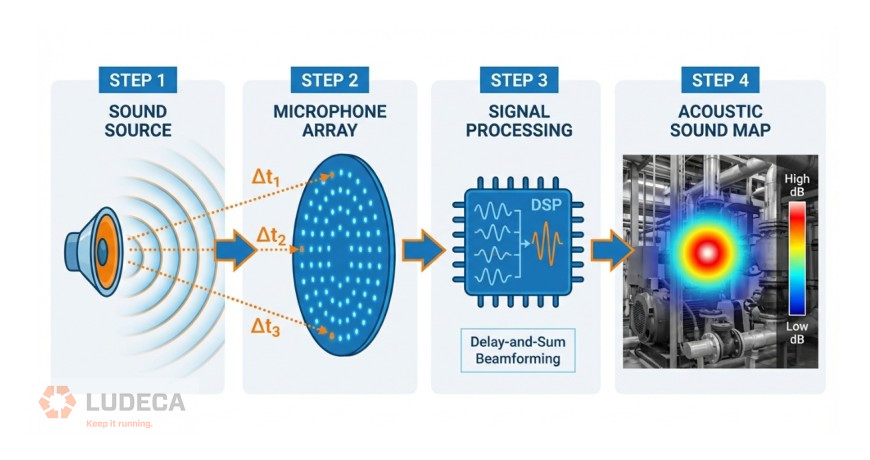
The key technology behind acoustic cameras is beamforming – a signal processing technique that combines signals from multiple microphones to “focus” on specific locations in space.
Here’s a simplified explanation:
- A sound wave arrives at each microphone at slightly different times (because each microphone is at a different distance from the source)
- The software calculates the expected time delay for every possible source location in the field of view
- For each candidate location, it shifts and sums the microphone signals according to the calculated delays
- Locations where the shifted signals add up constructively are identified as sound sources
This process is repeated for every pixel in the image, producing a “sound map” that shows the spatial distribution of sound energy.
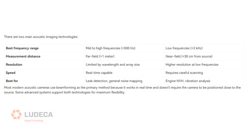
Beamforming vs. Acoustic Holography
The Role of the Video Camera
The microphone array generates a sound map; the video camera provides the visual reference. The software overlays the sound map onto the video feed as a color-coded heat map, allowing the user to instantly see which component, pipe, or connection is producing the sound.
High-end systems use depth cameras (such as Intel RealSense) to create 3D acoustic maps, enabling more accurate source localization on complex geometry.
Thanks to Crysound for sharing this educational blog! Click to continue reading, here’s a preview of what you’ll find:
- Frequency Range: Why It Matters
- Key Applications
- Types of Acoustic Cameras
- How to Choose the Right Acoustic Camera
- CRYSOUND Acoustic Camera Solutions
Filed under:
Ultrasound by Diana Pereda