
You’re scanning overhead pipework in a compressor room when your acoustic camera shows a bright hotspot on a steel support beam. You walk over, listen carefully, and check the surface. Nothing. No hiss, no vibration, no leak. The image looks convincing, but the source is not actually on that beam. This is one of the most common acoustic imaging false positives engineers see in the field. Acoustic camera reflections, beamforming artifacts, and background noise can all create ghost images or false hotspots that look like real leaks, discharges, or mechanical faults. That does not mean the camera is malfunctioning. It means the operator needs to separate true sources from indirect paths and side responses. Based on field observations in reflective industrial environments, teams often find that 15-30% of initial acoustic indications should be treated as leads for verification rather than confirmed source locations.
In this guide, we’ll explain why an acoustic camera shows false hotspots, how to tell acoustic camera reflections from real leaks, and how to reduce beamforming artifacts in noisy factories without slowing down your inspection workflow.
What Are False Positives in Acoustic Imaging?
False positive (acoustic imaging): An apparent sound source indication on an acoustic camera display that does not correspond to an actual physical source at that location. Caused by physical phenomena including sound wave reflections, beamforming algorithm sidelobes, or environmental noise interference – not by equipment defect.
Three related terms often get used interchangeably, but they describe different phenomena:
- False positive: Any indicated source that isn’t real at the shown location
- Artifact: A systematic error pattern produced by the beamforming algorithm itself (e.g., sidelobes)
- Ghost image: A reflected or mirrored source – real sound arriving from an indirect path
Understanding these distinctions matters because each type has different causes, different on-screen characteristics, and different solutions.
Why Acoustic Cameras Show False Hotspots
If your acoustic camera shows a hotspot on a wall, support beam, enclosure, or ceiling panel, the most common cause is a reflection rather than a leak at that exact surface. In other words, the hotspot may still be useful, but it is pointing to an indirect path instead of the true source location. If the display shows a halo, ring, or repeating spots around one strong source, that pattern is more likely a beamforming artifact than a second leak. And if the hotspot is broad, unstable, or spread across a noisy production area, environmental noise is usually a better explanation than a discrete defect. For teams using acoustic cameras in compressed air leak detection, it helps to pair this article with our acoustic camera guide and how acoustic imaging works explainer. If you need to quantify the cost of missed leaks before the next survey, use our air leak cost calculator.
Common False Positives in Acoustic Cameras

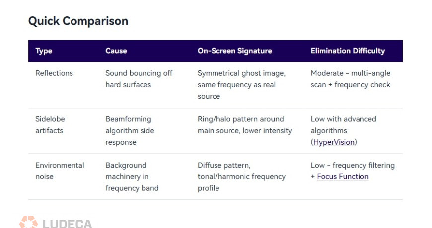
Reflections (Ghost Images)
Sound waves bounce off hard, smooth surfaces – metal walls, concrete floors, glass panels, polished pipes – just like light reflects off a mirror. When your acoustic camera picks up both the direct sound and the reflected sound, the reflected path appears as a second source at a location where nothing is actually producing noise.
- Typical scenario: You’re imaging a compressed air manifold mounted near a stainless steel wall. The display shows two hotspots – one on the manifold (real) and one on the wall behind it (ghost). The ghost image appears at roughly the same intensity and frequency as the real source.
- On-screen signature: Ghost images tend to appear at geometrically symmetrical positions relative to the reflecting surface. They share the same frequency spectrum as the real source and often appear at similar or slightly reduced intensity.

Sidelobe Artifacts
This is the most technically nuanced type. Beamforming algorithms work by mathematically “focusing” the microphone array on each point in the field of view. But just as a flashlight can’t produce a perfectly sharp beam edge, beamforming produces a main lobe (the focused area) surrounded by sidelobes – weaker response regions that can register false sources.
- Typical scenario: You’re imaging a single loud leak, but the display shows the main hotspot surrounded by a ring or pattern of secondary spots. These sidelobe artifacts are always clustered around the true source and become more pronounced when the source is loud relative to surrounding noise.
- On-screen signature: Sidelobes appear as a repeating pattern around the main source – often a ring, halo, or radial spoke pattern. Their intensity is always lower than the main lobe, and they maintain a fixed geometric relationship to the primary source regardless of scanning angle.
- Key factor: The number of microphone channels directly affects sidelobe levels. A 64-channel array produces more prominent sidelobes than a 128-channel array, which in turn produces more than a 200-channel array. Higher channel counts provide narrower main lobes and lower sidelobe floors. Advanced algorithms like CRYSOUND’s HyperVision processing further suppress sidelobes beyond what standard delay-and-sum beamforming achieves.
Environmental Noise Interference
Not every unwanted indication is a reflection or algorithm artifact. Sometimes, your acoustic camera is accurately detecting a real sound – just not the one you’re looking for. Background noise from HVAC systems, nearby machinery, overhead cranes, or even wind can register as apparent sources that get confused with your target.
- Typical scenario: During a compressed air leak survey in a manufacturing hall, you see multiple hotspots across a wide area. Some are genuine leaks. Others are background machinery noise that happens to fall within your selected frequency band.
- On-screen signature: Environmental noise sources typically have broader, more diffuse patterns than leaks (which appear as tight, focused hotspots). They also show different frequency characteristics – machinery noise tends to be narrower-band and harmonic, while leak noise is broadband and turbulent.
Thanks to CRYSOUND for sharing this educational blog! Click to continue reading, here’s a preview of what you’ll find:
- How to Identify False Positives: A 4-Step Process
- Techniques to Minimize False Positives
- Turning Artifacts into Allies: Using False Positives to Locate Sources
Filed under:
Ultrasound by Diana Pereda