
Early last year Bob Dunn with I&E Central, Inc. was approached by a customer with a unique measurement challenge. They needed to align two sheaves, 1 meter in diameter, separated by 12 meters (about 40 feet). While there are a number of sheave alignment tools available in the market, they employ line lasers, and their maximum distances are about 10 feet. Beyond that, for this application, there were physical barriers to projecting a beam right along the face or between the pulleys, so this required some application development.
They discussed with an associate and conceived a way to make this measurement using the standard detectors and programs on the Easy-Laser® E710 alignment system. The E710 is a high-end shaft alignment system with point (rather than line) lasers and 2-axis detectors with a working distance of up to 20 meters (66 feet). It also includes some basic geometric programs including straightness.
The customer’s goal was to align the sheaves in both planes, “horizontal” and “vertical”, within 0.1°. Going back to college trigonometry, 0.1° expressed as a slope is 1.745 mils/inch or 1.745 mm/meter. We can easily measure and calculate that.
The two sheaves were vertically oriented on a long superstructure with beams and supports extending about 10” out from the faces of the sheaves.
Here is how they made the measurement:
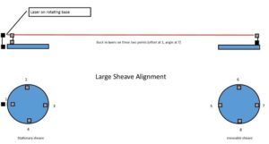
They mounted one of the laser heads (the “transmitter”) on a magnetic base with a rotating head. This magnetic base was mounted on the superstructure of the machine near the centerline of the stationary sheave, and aimed along the centerline. (See the graphic associated with this document.) The detectors themselves were extended from the magnetic bases with pairs of 12″ rods so that we had a clear measurement line along the structure.
They bucked in our transmitter between points 1 and 7 (see graphic). We did not need to set it to zero, we only needed the beam to hit the detector along the length of the measurement. Once bucked in, we used the straightness program and measured at points 1, 3, 5, and 7. Using points 1 and 3 as our reference line, the result indicated that the two sheaves were horizontally parallel within 0.05°, but were offset by about ½”.
Next, they measured the vertical alignment. Without moving the laser transmitter, they swept the rotating head and measured the slope from point 2 to 4, as 6.028 mm/meter. Then they performed the same measurement between points 6 and 8 (the far sheave), measuring 6.022 mm/meter – nearly perfect alignment (0.0003°).
The E710 proved to be a flexible and powerful tool that can do much more than coupling alignment. This new customer is already identifying additional measurements for their new system.
Filed under:
Alignment, Articles and Case Studies by Ana Maria Delgado, CRL