Guest post by Karl Hoffower – Condition Monitoring and Reliability Expert for Failure Prevention Associates
Location and placement of your sensors are crucially important when doing predictive vibration analysis.
1) Below is an example of proper sensor installation on a cooling tower gearbox. These two sensors are placed in different directions to follow both the gearbox vibration as well as indicate if the fan blades become unbalanced.
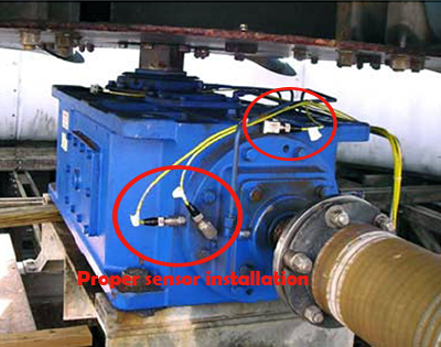
Read Vibration Sensors for Cooling Towers case study from CTC for details on proper sensor installation on cooling towers.
2) This example of poor sensor placement is on a vertical motor using a belt drive for a fin fan.
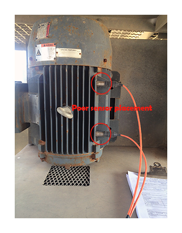
PROBLEM
- The vibration sensors pictured on the left are attached to one of the motor fins. Watching these sensors, one could visually see the fin and sensors oscillating as if on a trampoline.
SOLUTION
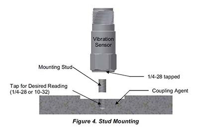
- The choices are to face, drill & tap (see figure #4 below).
- The other option would be to epoxy a mounting pad to the bearing housings. Then screw the sensor into the mounting pad.
3) Another example of poor sensor placement on a 4-20mA shutdown switch on a gas recipient compressor at a facility in Texas.
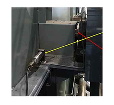
PROBLEM
- The vibration sensor (yellow arrow) is a 4-20mA accelerometer used for asset protection in an automatic shutdown setting. It is monitoring the overall vibration levels emanating from the bearings and shaft (red arrow).
SOLUTION
- The better choice would be to use a mounting pad attached to the pillow block bearing.
Filed under:
Condition Monitoring, Maintenance Tips, Reliability, Vibration Analysis by Yolanda Lopez