Centrifugal pumps come in a variety of shapes and sizes and are used in diverse ways to fulfill many different applications. These pumps deliver a life-sustaining liquid directly to our homes that is required for our very survival. For example, during emergencies, these pumps provide fire departments with the water needed to extinguish fires. Their value is critical, but their importance is often taken for granted.
Centrifugal pumps are designed to deliver a specific flow and pressure as dictated by the application. Centrifugal pump curves typically show the design-rated flow (usually expressed in gallons per minute or GPM) across the X-axis of the curve and the pump’s total pressure (total head) along the Y-axis. Different size impellers can be installed on these pumps depending upon the design requirements. The engineer must accurately calculate the required operational parameters because once installed the pump will operate at the point where the system head intersects the pump curve.
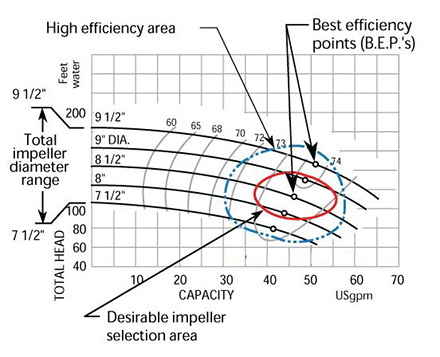
Based on the pump curve below, several different impeller diameters can be utilized for this specific pump ranging from 7½ to 9½ inches. In our hypothetical system, we have calculated a total system head of 100 ft. and we need 50 GPM for sufficient cooling in our manufacturing process. Based on our calculations an 8½ inch diameter impeller would result in the pump meeting our design point of 50 GPM @ 100 ft. head @ 73 % efficiency.
So far everything is working out perfectly for our project, but if the system head is not calculated correctly or the pump is ordered with the wrong diameter impeller we will have process and reliability problems.
If the correct diameter impeller (8½ inches) isn’t specified, then the pump manufacturer may simply supply the pump with the maximum diameter impeller (9½ inches). If we installed our new pump with the wrong size impeller it would operate well to the right of the required operating point of 50 GPM @ 100 ft. head. This would result in excessive vibration levels, motor overload, reduced bearing life, seal problems, and cavitation problems.
As a result, we would experience higher maintenance costs, higher operational costs, reduced MTBF, and reduced pump efficiency.
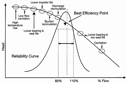
The chart below shows that centrifugal pumps are usually most reliable when operated from 80% to 110% of their best efficiency point (BEP). Outside of this range, unwelcome reliability problems will occur.
The scenario above occurs more often than realized! Many pumps are operated outside of their best efficiency range and unwanted consequences are experienced. A good reliability program will always seek to determine the root causes of failures. Simply replacing failed components such as worn impellers, damaged bearings, etc., does little to address the root cause of the problem. Not understanding why a component failure will doom you to replace it again in the future and true reliability gains are not made. Proper equipment specifications and design are critical in ensuring long-term reliability. It is very difficult or impossible for maintenance to overcome poor design or specification. Centrifugal pumps that are specified properly for the application, correctly installed, aligned, and balanced will increase your pumping system reliability. This will lead to reduced maintenance costs, improved uptime, and other valuable results.
Filed under:
Condition Monitoring by Dave Leach CRL CMRT CMRP