The consequences of positional change due to thermal growth in machinery as it pertains to shaft alignment are well documented. Methods for determining these changes and compensating for them are not only essential to the reliability of machines but can prevent catastrophic failure. It is therefore of great importance that these methods be carried out as carefully as possible—minimizing human error as much as possible to ensure effective results.
One often-overlooked consideration when performing shaft alignment measurement is the temperature and thermal stability of the very components used for these measurements. Brackets, lasers, sensors—all components that are susceptible to thermal growth. Changes in the intensity of sunlight, large shifts in ambient temperature during the job, and performing measurements too soon after bringing the components out to the machine can all lead to lack of repeatability and improper shaft alignment corrections.


You can minimize the effects of these conditions in various ways:
- Always allow a suitable amount of time for the alignment system to acclimate to the environment in which you will be performing the measurements. For example, if the equipment is moved from a warm office or truck to a cold environment and measurement is begun immediately without giving the temperature of its components enough time to stabilize, performing the shaft alignment will be a bit like trying to hit a moving target. The brackets and/or laser and sensor housing will still be physically changing in dimensions until stabilization has occurred.
- If sunlight conditions are unstable where you are working try to keep the alignment components shielded from the sun. Direct sunlight striking the laser housing of a shaft alignment system can have an adverse effect on the reliability of the readings during a measurement.
- Keep portable heaters and air conditioning units away from the area. It is natural to want to work in a comfortable environment, but the unstable air currents caused by heaters or a/c’s can wreak havoc on measurement repeatability.
- And one more: if a heat source is intense causing heatwaves in the path of the laser beam, thereby distorting or refracting the laser beam and affecting your repeatability, a simple fan to blow air through that area can help to stabilize conditions or provide a uniformly turbulent atmosphere for the laser to travel through, allowing its true position to be accurately averaged.
Observing these principles while performing shaft alignment readings will allow you to achieve more stable and reliable results and thus help you to #keepitrunning.
For more information, check out our Shaft Alignment Know-How: Thermal Growth and learn the importance of accounting for thermal growth on rotating equipment.
by Diana Pereda
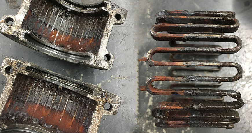
There are a lot of numbers and stats associated with lubrication; or, with the lack of proper lubrication in this case. For instance, it is said that 60% – 80% of bearing failures are related to lubrication issues of some kind; lack of lubrication, over- or under-lubrication, mixing lubricants that are incompatible, choosing the wrong lubricant for the application (such as the wrong grease or wrong viscosity oil), and finally, simply using a lubricant that is contaminated from the start.

The key to proper precision lubrication starts with the right mindset. We must believe that the lubricant is an “asset” and not just an ugly necessity. If we turn our mind towards precision lubrication with the precise “asset” for the application then our success rate for uptime will skyrocket. Think of trying to use a Philips head screw driver on a slotted screw. Simply put, it is the wrong tool for the application.
If we use a lubricant that is contaminated from the start, what chance are we giving the asset for success? What can we do to make sure the lubricants used are in the best condition for optimum performance? Let’s start at the beginning when the oil or grease first arrives at the receiving dock.
1. If we are receiving an oil, take a sample of the oil to make sure it is the oil that was ordered (proper type: hydraulic, gear, turbine, etc.), and is of the proper viscosity. Then check the cleanliness (particle count/ISO Cleanliness code) in which it was received from the supplier. Set it aside and wait for the results of the analysis before using.
2. Once we get the results back and are satisfied we received what was ordered, we should filter the oil with a kidney loop filtration system of some type because we know that new oil is not clean oil: especially hydraulic standard clean. Filter the new oil before using.
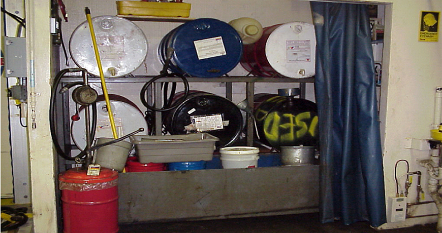
3. Take extra precautionary steps when filling the asset with the now clean oil so as not to contaminate the system with debris that has surely gathered on the asset. Best practice would be to have a completely closed system which filling with oil would require quick-connect adapters so the new oil can be transferred without ever having to open the system by fill port or by removing a lid. If this is not an option, make sure the transfer containers are color coded and sealed; do not use an open container or an open galvanized container. Be very careful not to inadvertently allow debris into the system.
4. The asset itself can be adapted for better success by implementing a desiccant breather, closing fill ports with quick-connects for filling and external filtration and perhaps a bottom water and sediment bowl for water and debris detection and removal.
5. The asset should have a label that matches the label on the oil container in the store room, the oil transfer cart and/or the color coded transfer container.
6. Implement an oil analysis program and keep an eye on the oil and asset health. If the sample comes back with good viscosity and additive levels but is dirty then filter it with the kidney loop system and get the oil back to the desired cleanliness level. Investigate where the particulate is coming from and take steps to prevent future particulate intrusion.
In conclusion, while there are many more steps we can take to maintain a healthy oil and therefore a healthy asset, these are some obvious action items we can implement for better success. Imagine if we turned the negative numbers of 60% – 80% into positive numbers for the company. Clean, healthy oil is an asset for success.
Download our Oil & Grease Storage Best Practices for additional tips to help outline the best practices for proper lubrication storage.
by Diana Pereda


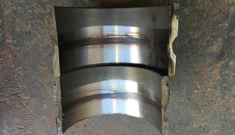
Many shafts have keyways cut into them to hold the coupling. “Keys” are pieces of square metal stock inserted to hold the hub in place.
If there are two (2) keys, one on each side of the coupling, you should not “align” the keys across the coupling. Instead, it is very important to ensure the coupling mass is balanced during installation. The mass of a key is balanced by setting the two keys 180 degrees apart from each other. If the keys are set on the same side, the coupling will induce a mass unbalance situation.
Often a vibration report will note a misalignment condition, but precision alignment techniques will not find any issue. This can lead to friction between the vibration analyst and the millwright. Keep the keyways 180 degrees apart. You will help improve the life of the coupling and keep the vibration low.
by Diana Pereda
Every person that performs vibration analysis develops his or her own analysis process. Suggested steps at a minimum should include:
- Open the spectrum (FFT) and locate the running speed peak and reset the reference speed to that speed. Since all induction motors vary in speed based on the load, this is necessary for accurate analysis, particularly at multiples of running speed.

- What are the dominant peaks?
- Are there any other peaks of interest?
- Where is the primary energy located?
a. Is it sub-synchronous, synchronous, or non-synchronous? - Do the waveform patterns support the peaks in the spectrum (FFT)?

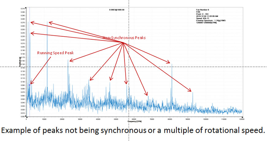
- Remember that defects follow patterns. Some defects happen at frequencies less than running speed (sub-synchronous) or at running speed or at multiples of running speed (synchronous), or at frequencies greater than running speed but not at whole integers (non-synchronous).
- Learn pattern recognition and don’t overlook the obvious.
- Generally, most equipment doesn’t have only one issue going on, learn to sort out the various problems and tackle the worst one or ones first.


Test Your Vibration IQ and see how much you know and maybe learn something along the way!
Related Blog: The Importance of Vibration Analysis
by Diana Pereda


Once again, I was struck by a smart sign that reminded me of the importance of safety: “TAKE FIVE for SAFETY.” This one popped up while touring the APM Training and Development Center in Houston, Texas after our #NoExcuses for Equipment and Bearing Failures workshop.
It was the perfect closing theme to a day of learning how planned and precision maintenance practices, along with step-by-step procedures, not only reduce equipment failures but, most importantly, move us away from rushed reactive work that increases the risk of personal injury.
We had started our learning day taking five minutes to review safety procedures in the building. Later during the tour of the amazing APM training facilities, we had taken five to put on our personal protective equipment (PPE) to get near their mega GE turbines. Their commitment to safety at all times prompted me to share with you my five takeaways from our workshop for reliable work that will also deliver safety:
- Prepare and plan your work. This quote from President Lincoln reminds us of the importance of preparation to get the job done right:
Give me six hours to chop down a tree and I will spend the first four sharpening the axe.” ― Abraham Lincoln


- Torches, rosebuds, and oil baths are not safe methods to heat your bearings, as they will almost surely result in burns and damage your bearings. Instead, consider heating your bearings and other workpieces using safe induction heating. It’s a clean, faster, and more accurate method, whether in the shop or in the field and best of all, safe!
- Electrical faults are dangerous! Taking five to reduce personal injury by adding ultrasound to inspect your electrical systems for arcing, tracking and corona is the best work safety practice.
- Also, use ultrasound to detect dangerous leaks such as gas and ammonia before you step in there and breathe it in.
- Protect your assets, both people and equipment, by implementing the following five steps along with precision maintenance technologies:
- Stop and think about the potential dangers associated with the job.
- Look for and identify any hazards.
- Assess the risk; consider any possible risk of damage or injury.
- Control hazards by implementing suitable control measures to reduce the risk.
- Monitor hazards to successfully mitigate the likelihood of injuries or damages as you work.
Further, I found this information about “Take 5 for Safety” that you may find useful for your facility:
The above-listed Take 5 Safety checklist is a tool used to identify health and safety hazards before starting work at a site. Performing health and safety checks using the take 5 procedure (Stop, Look, Assess, Control, and Monitor) helps workers and contractors mitigate exposure to injury hazards and health risks.
Source: SafetyCulture
Click here if you missed and want to read my previous safety post: Heaven can wait! Safety first. Always lock-out and tag-out your machines.
by Ana Maria Delgado, CRL


- RMS – use it to indicate trends in friction levels (lubrication, stage 1&2 bearing failure)
- Max RMS – use it to indicate ultrasound signal stability (steam traps, chain drives, flexible couplings, linear bearings)
- PEAK – use it to indicate impacting (shift from stage 2 to stage 3 bearing failure, fatigue, gear mesh, broken gear teeth)
- Crest Factor – use it to correlate the relationship between friction and impacting on any asset (perfect for VFDs!!)
- Gas & Valve Leak – RMS
- Lubrication – RMS
- Steam Trap – RMS & Max RMS (+Peak for flash steam)
Impacting:
- Bearing, Gears – Peak & RMS (+Crest Factor)
Cavitation:
- Cavitation – Peak
Check out our SDT 200, 270, and 340 featuring the four condition indicators to detect, trend and analyze ultrasound and vibration.
by Diana Pereda
It seems a simple question, yet when asked, the answers are not always similar, or simple.
Some say, “to fight friction” and that is true. We do add grease to an asset’s moving parts to reduce friction. But there’s more to it than that.


Some say, “to reduce heat” and that is also true. The right amount of lubricant does help keep moving parts from getting too hot. But some lube techs, thinking more is better, take it to the extreme. They add more grease — thinking they are doing good — and instead choke the machine’s ability to disperse heat.

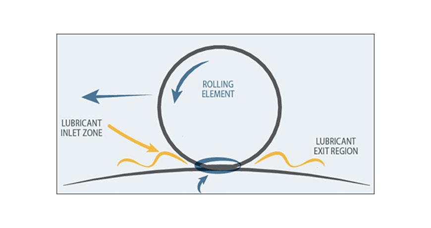
The real reason to lubricate assets is to form separation between surfaces. This logic applies to not only motor bearings. The pistons in an engine, chains on a chain drive, gears in a reducer, even linear bearings that do not rotate, but slide back and forth. The primary purpose to lubricate physical assets is to keep moving surfaces from coming into contact with each other. Because when they do, failure modes are initiated, and lifecycle is shortened.

Friction is a force which opposes movement between surfaces. Friction increases wear between surfaces, increases system temperature, and dramatically increases power consumption. The right amount, and type of lubricant creates a thin film between two surfaces. For as long as that film is maintained, it protects the asset from wear and heat while allowing it to produce in an energy efficient way.
Some lubricants offer the additional benefit of controlling corrosion. They contain additives which prevent rust from acid and water attacks.

Grease must be kept free of contaminants, but the very nature of the thickener allows it to pick up dust and grit. Proper storage is therefore crucial, and clean grease applied properly can actually shield machines from the ingress of contaminants.
The science of lubrication continues to evolve for over 4000 years. But the principles remain the same; to maintain separation of two or more surfaces, thus prolonging the reliability of the entire asset.
We welcome you to read the previous blog in this series, “Three Myths About Greasing Bearings.”
Download our Oil & Grease Storage Best Practices for more tips to help outline the best practices for proper lubrication storage.
by Diana Pereda
I attended a training recently on the Easy-Laser XT770 alignment system at an oil and gas fracking company in West Texas. During the training I heard the term “grease worms” and even though I have been in the lubrication field for 29 years, I was unfamiliar with this animal.

Come to find out, it is a term used to describe an application completely devoid of any grease. In other words, someone didn’t grease the equipment at all and according to the guilty parties, these fictitious “grease worms” must have eaten the grease!
That got me thinking about the different oil viscosities and grease thickeners and how not all greases are created equal. We must look at each application individually and determine the correct oil viscosity and the correct thickener or “soap” that will work best in the application. You see, the thickeners have different characteristics that affect the performance. The term “LETS” can get us close to our final selection.
- Load – what load will the bearing be supporting during its life cycle? Heavily loaded bearings are typically slower moving and would require a more viscous base oil to help separate the metal surfaces moving opposite each other. I might choose a calcium sulfonate thickener for this application because this thickener has excellent load carrying capabilities.
- Environment – where will the bearing be located? Is it outside, exposed to the elements? Is it in the fracking world where water, dust, dirt, vibration, rain, or chemicals etc. will have an effect on the grease’s performance? Choose the thickener wisely as now a lithium complex or aluminum complex soap may be the best general purpose option.
- Temperature – In West Texas, the temperature swings can be 60 degrees from night to day. This might affect the performance of the grease as it relates to pumpability, especially in an automatic grease system like this facility was using. Now, the thickener might deter the flow of the grease as some soaps are known not to pump well, like a calcium sulfonate.
- Speed – what is the bearing speed? Faster and smaller typically have the need for a lighter viscosity base oil and a more flowable thickener. Conversely, a large, heavily loaded slow moving bearing would require a more viscous base oil and a more robust soap to help carry the load.
In conclusion, LETS investigate each application on its own merits to make the best final determination for which grease should be used; and, precision lubrication using ultrasound can help ensure that the right amount of grease is being used, and might just help avoid the infiltration of the dreaded “grease worm”!
by Diana Pereda
Once you understand how grease actually works to lubricate a bearing, it becomes obvious why over-greasing causes so much trauma to both bearings and the grease itself. Remember, all we want from our lubricant is to provide a little separation in the war zone. Nothing more… nothing less.

If you’re reading the term “war zone” for the first time, we use that term to describe the region of the bearing where all the wear and tear occurs.
Now let’s dispel three myths about greasing bearings.
Myth #1: if some grease is good, then a lot more must be great.
- WRONG! Most bearing manufacturers like SKF, FAG, NTN, KOYO, all recommend that the bearing housing cavity only be filled to 30% capacity. Lube departments using a time-based approach to grease replenishment are almost always leaving their assets in an over-greased state.
Myth #2: More grease will provide better cooling for the bearing.
- WRONG! Grease doesn’t provide cooling, air space does. Filling every void with grease chokes the bearing’s ability to dissipate heat generated by even normal friction levels.
Myth #3: If there is a grease nipple on the bearing housing it must be greased.
- WRONG! Some motors come with “sealed-for-life” bearings installed. These are meant to be never greased… EVER. Yet, someone thought it would still be clever to install a grease nipple anyways. You have to know what’s inside your motor because grease guns are like toothpaste. Once you squeeze the trigger you can’t stuff the grease back inside the tube.
Enough bad practices, please. We need a greasing strategy, but more than this, we need a greasing culture. Bad greasing culture will eat good greasing strategy for lunch. It only takes one bad actor, often well-intentioned – to destroy an asset.
Grease guns don’t kill bearings… people do.
Thank you Allan Rienstra with SDT Ultrasound Solutions for sharing this informative article!
Check out our LUBExpert, the ultrasound solution to avoid grease-related bearing failure! Plus, download our 5-Step Acoustic Lubrication Procedure an effective lubrication procedure to grease bearings right.
by Diana Pereda
While in Louisville, KY after the #SMRP19 conference, I took a tour of the Angel’s Envy bourbon distillery and was thrilled not only by their fine bourbon finished in port wine barrels but by their attention to safety and unique promotion of safety all around their clean facility. Their clever “Heaven can wait. Safety first” statement obviously applies to all maintenance activities but in this particular case, shown in my photo, it was used to emphasize the importance of lock-out and tag-out procedures, also known throughout our industry as LOTO.


It reminded me of what we assiduously preach in all of our training courses: always lock out and tag out your machines before beginning any alignment procedure or balancing procedure.
Unlike ultrasound testing, acoustic lubrication or vibration analysis, all of which check machine or facilities condition while up and running, alignment and balancing require machines to be shut down and properly locked out, to adhere to all safety regulations. Only then can the components be mounted on the shafts. This ensures the safe rotation of the shafts and alignment corrections to be made without risk of injury to maintenance personnel.


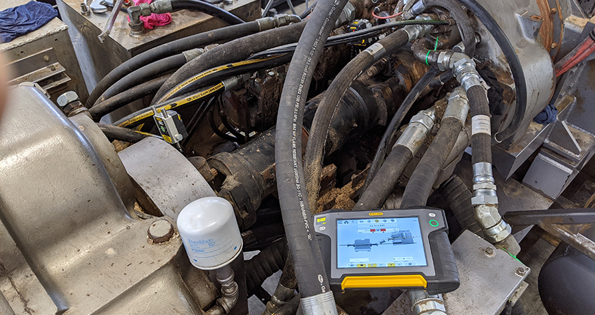
Thank you, Brian Franks with JetTech Mechanical for these great field photos featuring the Easy-Laser XT770!
I can’t stress enough the importance of safety during service or maintenance of machines and encourage you to develop more ingenious slogans like “Heaven can wait. Safety first” to draw more attention to this important concern within your plant.
Here are the six steps to follow for proper LOTO per OSHA 3120:
1. Prepare for shutdown;
2. Shut down the machine;
3. Disconnect or isolate the machine from the energy source(s);
4. Apply the lockout or tag-out device(s) to the energy-isolating device(s);
5. Release, restrain, or otherwise render safe all potential hazardous stored or residual energy. If a possibility exists for reaccumulation of hazardous energy, regularly verify during the service and maintenance that such energy has not reaccumulated to hazardous levels; and,
6. Verify the isolation and deenergization of the machine.
Source: Control of Hazardous Energy Lockout/Tagout. OSHA 3120 – 2002 (Revised)
A personal note for Bourbon lovers: if you haven’t already, try pairing dark orange chocolate with your favorite bourbon, what a delicious combination! Heaven can wait. Please drink responsibly.
by Ana Maria Delgado, CRL


Compressed air is one of the three highest cost utilities in use at your plant. It is also one of the least maintained in terms of system leaks. Leaks are expensive and wasteful, but most often ignored. Leaks may occur anywhere in your compressed air system. Here’s our list of top ten most common leaks:
- Connections on air supply lines (pipes)
- Quick couplers
- Filters
- Pneumatic cylinders
- Pressure regulators
- Air dryers
- Isolation valves
- Control valves
- Automatic drain traps
- Air separators
Finding and fixing these leaks is an easy way to reduce energy costs, but finding them is not easy because of background noise. A good quality ultrasonic detector can hear turbulence despite the ambient noise of the factory floor.
Download our LEAK SURVEYORS HANDBOOK and learn how to reduce or eliminate wasted compressed air with ultrasound through effective leak detection and repair.
Source: Ultrasound Leak Surveyor’s Handbook by SDT International.
by Diana Pereda
A route for vibration programs is the order in which machines that need to have vibration data collected on them have that data collected. To be able to optimize the data collection time and effort, the best practice is to have multiple routes. The machines in the route should be listed in a strategic and time saving list. If you were walking through the plant, which machines would be reached first, second, third, and so forth. The order of the routes themselves is very important as well and the time it takes to gather the data. If some machines (such as slow speed gearboxes) take a lot longer to collect data on, then perhaps a separate route might be needed just for them.
If the routes are not in a logical order then additional time is needed on the instrument to select the correct machine to start data collection. While 10 seconds might not seem that long to select the correct machine, if you have 200 machines on a route it could easily take an additional 30 minutes to finish that route if it is not logically configured. Data collection on that one route each month for the entire year could quickly turn into 6 hours of wasted time. Most plants have multiple routes and this wasted time figure could increase very quickly.


Routes are only the list and sequence of the equipment and do not hold any data themselves (within the VibWorks systems) and can therefore easily be deleted and re-created as many times as needed.
Reviewing your routes yearly could assist in eliminating wasted time.
by Diana Pereda
Problem
Dirt particles as small as 5 microns can easily damage bearings and gears in equipment. Unfortunately, gearbox vents and hydraulic breather caps only prevent particles larger than 25-45 microns from being ingested into machinery from the surrounding air. As a result, those large particles are broken down into much smaller particles resulting in premature equipment damage. For example, one teaspoon of dirt in a 55 gallon drum of lubricant can create one billion particles that are 4 microns or larger in diameter in that same drum. Imagine how much damage this can cause in equipment, leading to unwanted maintenance downtime.
Additionally, these vents and caps provide no protection from moisture ingress into equipment. Water is one of primary defect sources for industrial machinery.
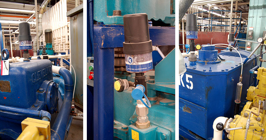
Solution: Install good quality desiccant breathers on your equipment
A good quality desiccant breather has a 3 micron filter as part of the design to help prevent harmful particles from being introduced into equipment. As a result, premature equipment failures, loss of capacity and unneeded maintenance expenses will largely be prevented.
Additionally, desiccant breathers provide an insight into the equipment health through how the desiccant is being spent.
It is very important to have good quality desiccant breathers installed on equipment to prevent the introduction of equipment defects and help improve your return on assets.

Desiccant Breather Assessment
- If the top of the desiccant breather is pink there is an internal moisture source from the reservoir headspace.
- If the bottom of desiccant breather turns pink first then there is an external moisture source from the outside environment.
- If the desiccant breather turns amber or brown instead of pink, then it is likely an indication of oil misting.
- If the breather has turned completely pink then the desiccant is spent and the breather is at full water saturation.
- Reservoir water content: If the breather changes quickly from blue to pink when first installed, then the breather is likely working to remove water already in the system. It may take two to three breathers to dry the headspace before the breather begins operating normally.
- Sizing: If breathers continue to spend quickly, the size may not be appropriate for the application.
Things to check if your breather is not spending at all
- Dry Environment: If the environment has been abnormally dry there may not be enough ambient moisture for the silica to adsorb.
- Breather Size: The breather may be larger than what is required for the system. Check the recommended system sizing. The breather should be changed after one year, regardless of visible condition, to renew particle filtration.
- Intake Holes: Check that the proper number of plugs have been removed. Instructions on the breather packaging indicate how many holes are needed for various air flow requirements.
Note: The actual color changes above will vary depending on the supplier of the desiccant breather. All breathers will have some type of color change indicating condition. The above colors are applicable to two well-known desiccant breather manufacturers.
Desiccant Breather Air Vent Plugs
- Some combination of air vents should always be pulled depending on the air flow in the machine. This is a common mistake when installing breathers.
- If the CFM is greater than 12-16 CFM you should pull all of the air vents from the breather.
- When selecting a breather, always select a model with a CFM rating greater than the CFM requirements of the application.
- Breathers should not be selected by the size of the tank or reservoir. Breather size is always determined by the maximum fluid movement in/out of the fluid reservoir.
- Not all equipment, for example gearboxes, may specify a CFM value. If needed you can use this rule of thumb o calculate the CFM and select the correct breather for the application:
7.5 GPM = 1 CFM.
CFM = GPM/ 7.5.
Learn more about Lubrication Best Practices and desiccant breathers from Paul Llewellyn at our Rethink Maintenance Training Roadshows
by Diana Pereda

- Prevent metal-to-metal contact (which creates wear particles) by using condition-based lubrication through ultrasound. Ensure the proper oil viscosity and additive package is selected and that the bearing load does not exceed its design capacity through proper installation, alignment, balancing and operation.
- Use desiccant breathers.
- Adopt an aggressive fluid management program that establishes acceptable ISO cleanliness targets for new oil by machine type. Take care to use methods of adding and sampling oil that minimize contamination ingress. These include quick connect couplers and point-of-use filtration. Install an oil recirculation system to remove particles as soon as they are created and introduced.
by Yolanda Lopez
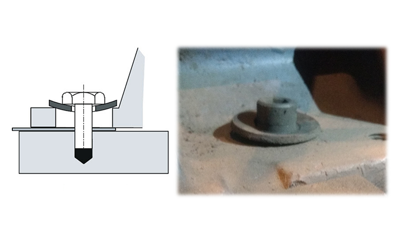
 Often, maintenance departments invest in good quality Bolts and Nuts (Grade 8), but neglect to do the same with flat washers. The importance of a good washer cannot be overstated. If you use a typically thin Grade 2 (or worse) flat washer under the bolt head of the hold-down bolts of your machine, this washer will easily be distorted or warped into the hole in the foot upon tightening the anchor bolt. This is particularly true if the difference in shank diameter of the bolt and hole diameter in the foot is significant. This will often be the case when the hole in the foot has been enlarged to overcome a bolt-bound problem. The result of having “dished” washers is that when the anchor bolts are tightened after completing the alignment, the washers will try to center themselves in the hole in the foot and in doing so will pull your machine out of alignment again. This effect is virtually impossible to overcome, resulting in a badly misaligned machine after you just did a good alignment!
Solution: Always discard warped washers and use high quality thick flat washers that will not distort or warp into the hole. This will allow the washers to do their job of supporting the bolt head’s load on the surface of the foot.
Take a look at our Shaft Alignment Tools!
by Yolanda Lopez
 An overall level is a single number representing the amplitude of a vibration measurement. Overall values can be derived many different ways. You should be very cautious when assigning generic or the identical alarm values to your equipment. Similar machines can operate at different vibration levels. The individual characteristics of each machine should be taken into consideration when setting valid alarm levels. Even a simple vibration check revealing acceleration, velocity, unbalance or bearing noise can help you find and prevent equipment faults. You don’t need a sophisticated system for this; just a simple but good handheld tool (such as the EASY-LASER XT280) can help you with this.
by Ana Maria Delgado, CRL
Compressed air is the fourth most commonly used source of energy in industry. Walk through any facility and see miles of pipe transporting this house-made energy source to its point of use. On this journey its fate is undecided. Will it arrive to deliver the intended value? Or is it lost along the way?
Why Do We Tolerate Leaks?
On average, 40% of compressed air goes to satisfying the false demand of leaks. Why do we tolerate this waste in an otherwise efficient economy? Lots of reasons.
- Low Safety Risk?—Compressed air Leaks are rarely considered a risk. Odorless and colorless, they don’t make a mess on the floor, and we can’t hear them over plant noise.
- Lack of Education—Many believe compressed air is free. Yet a leak costs a thousand times more than lights that are left on.
- Complacency—The reliability culture does not always extend to the compressor room. Energy efficiency must be written into an organization’s aims and objectives.
Facts and Figures Don’t Lie.
Air is free. Compressed air is not. It requires another energy source to compress it. How much energy? Here’s the cost breakdown of a typical compressor system:
- 13% CAPEX
- 12% Maintenance
- 75% Energy
A small compressed air leak can cost $2,000+/year. Consider that hundreds of leaks may exist in your facility. What are you waiting for?
Leak-Management Solution
Manage your leaks with ultrasound. Their turbulent flow produces sounds that generate peaks in the 35kHz to 40kHz range—exactly where SDT’s ultrasound detectors are engineered to perform. SDT pinpoints leaks at their source, regardless of background noise.

 Use our Airborne Ultrasound Leak Management: Find-and-Fix Leaks, and start reducing waste plus save money!
Download our Leak Surveyors Handbook to learn more!
by Yolanda Lopez


MYTH: “All Soft Foot can be corrected by proper shimming.”
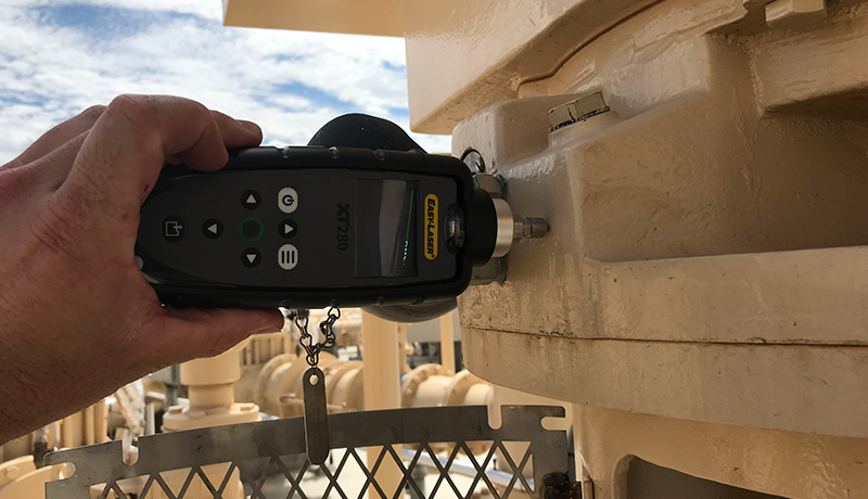
TRUTH: Soft Foot is Machine Frame Distortion. This can sometimes be caused by problems not easily fixable by shimming, like pipe strain, which can only be properly corrected by adjusting the piping and interface with the machine. A good laser system with positional change monitoring capability (such as EASY-LASER XT770 with Easy-Trend) is the best way to detect and measure the effects of pipe strain.
Watch and learn more about Soft Foot!
by Yolanda Lopez
Is it bearing information, number of poles, frame size, number of gears, impellers, blades, horse power, operating voltage, motor type, manufacturer, number of belts, sheave size, or tooth count? Nope! None of the above.
All of the above information is great to have when analyzing vibration data, but the single most important item that is always required is the running speed of the equipment.
Not knowing the true running speed makes vibration analysis impossible for determining the proper defect to be reported. For example, if the speed was recorded at 1,780 RPM, but the true speed was 3,560 RPM and a high peak at 3,560 RPM is present; it could lead the analyst to believe that the 2× turning peak is related to another issue. Having the proper running speed of the equipment will assist the analyst in making the correct diagnoses for the equipment.
Once the correct turning speed has been identified the spectrum can be broken into three types of energy: sub-synchronous, synchronous, and non-synchronous.
Having this information available can assist the analyst when analyzing the vibration data.


Related Blog: Finding the running speed of a machine
by Yolanda Lopez
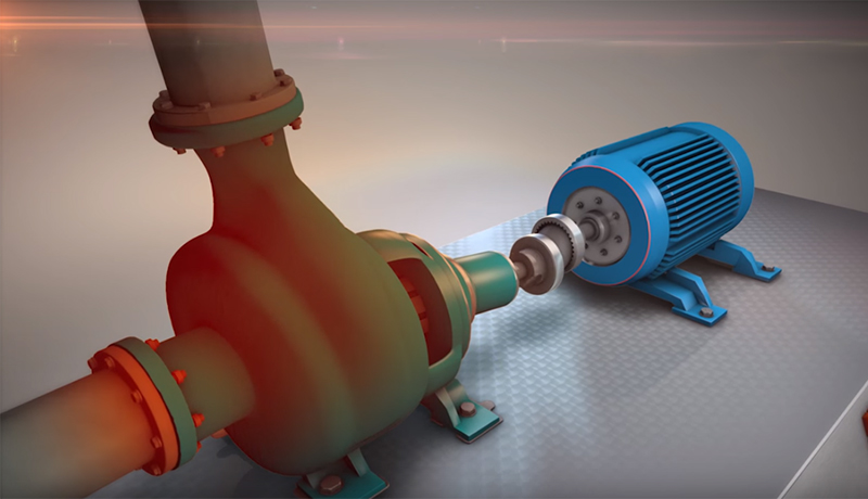

MYTH: “Pipe Stress makes the alignment difficult.”
TRUTH: Pipe stress does not have any significant influence on the alignment unless you make corrections on the machine with the piping attached. In most alignment, the corrections to eliminate misalignment are performed on one machine only, typically the one that is easier to move. In a pump-motor set, the corrections are done on the motor. If there is sufficient room to shim and move, excellent alignment can be achieved regardless of how much pipe stress there is on the pump. Of course, pipe stress is undesirable and should be eliminated prior to the alignment.
Watch and learn more about Pipe Stress
by Yolanda Lopez