Often, when I get a report or a technical support call, if I see the user got a perfect “0-0”, I become immediately suspicious rather than celebratory. What I mean by “0-0” is that the coupling results or feet corrections (or both) are perfect zeros. There are times where that is possible, for example, this screenshot of the alignment that was taken out in the field as shown below:
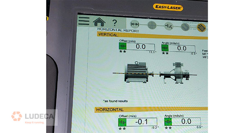
The numbers are close to zero, but not exactly zero. The point is there is at least some variation. Assuming the resolution is set to the nearest 0.1 mil, “0-0” would mean that that alignment is less than 0.1 mil, a very rare and impressive achievement!
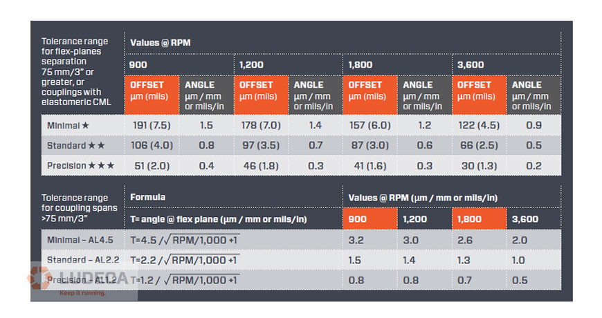
Is “0-0” necessary? The answer is no because you have a shaft alignment tolerance for a given speed of rotation. Lower rotation speeds require looser tolerances and higher rotation speeds have tighter tolerances. Tolerances are to be used to your advantage so you know when to stop the alignment. If the goal is perfect zeroes, it could be possible, but you will be working way too long to achieve a nearly impossible goal. We suggest the use of the ANSI/ASA S2.75-201 standard tolerance as shown below:

What happens if you do get “0-0” for your alignment? I would advise checking the following to make sure this was not a user setup error:
- Check the resolution. Is it set to 0.1 mil resolution (recommended)? If it is set to 1.0 or even 10.0, the lowest number will default to zero.
- Are you using the correct units? (i.e. metric vs imperial)
- Is the measurement shown to repeat in the measurement table? Is the alignment measurement reproducible?
- Were the sensors mounted on each machine shaft? Never mount the sensors on the coupling part that flexes, or you will get an incorrect reading. If you mount on the coupling only, this doesn’t represent the alignment between the machines; you will have an incorrect setup and most likely show perfect alignment.
- If you have a solid boss fit style rigid coupling, make sure the boss fit is separated to disengage the coupling with the bolts slightly loosened. This allows the misalignment to be measured. If the coupling is bolted, the shafts will be forced together, showing an incorrect near-perfect alignment.
Request your complimentary copy of our Shaft Alignment Fundamentals Wall Chart which highlights the ANSI/ASA Shaft Alignment Tolerances as well as information and guidelines for the implementation of good shaft alignment of rotating machinery, best practices, soft foot, tolerances, thermal growth, and much more!
Filed under:
Alignment by Daus Studenberg CRL